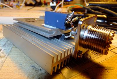
DIY 50Ω dummy load w/ peak detector
Having ordered a used mobile radio from eBay, I felt that I needed a dummy load for tuning and testing. While I was at it I figured I'd add a peak detector to get a reasonably accurate power measurement at the same time.
I pulled two bits of heatsink that came from an old PC power supply, an AC filter capacitor and a couple of signal diodes from the junk bin. To go along with them, I ordered a UHF connector and 1% Caddock 50Ω 60W non-inductive power resistor (MP2060-50.0-1%, about $7 at DigiKey). It comes in a transistor-like package, but sans mounting hole, so I'd have to clamp it with something. After fiddling around with placement and the position of the existing holes in the heatsinks I found an arrangement that would work well enough, dabbed on some thermal compound and screwed it together.
After soldering the resistor to the SO-239, I placed two 1N4148 diodes in series with the centre conductor, then to a 0.33μF capacitor to act as a peak-hold. The other side of the capacitor connects directly to the SO-239 body for ground. There's an integral ~160kΩ resistor across the capacitor for safe discharge; I just left it in, it shouldn't appreciably change the impedance of the load and might save me from an annoying shock when used at higher power levels.
To measure power output, measure the DC voltage across the capacitor, add the diode drop (measure this ahead of time, I wrote it on the load with a Sharpie), then divide by √2 (1.414) to convert the stored peak voltage to the RMS voltage of the corresponding sine. Then simply use the power formula ( \(P = \frac {V²} {R}\) ) with R = 50Ω to get the power output in watts.
The load seems to work fine with the TG-UV2 and doesn't get noticeably warm transmitting at 5W for short periods. Now I need a less-lossy PL-259 jumper to get a reasonable measure of power output from it; my cheap 50' feedline is dumping at least 2.5dB of the signal. That said, the measurements seem reasonable based on that fact.
