Clock-Block Knock Off
A while back I spent some time building a stratum 1 NTP time server based on a Motorola Oncore UT+ GPS receiver and an old (decommissioned and free) PC Engines WRAP.1E-1 board. I was inspired by N8UR's (John Ackermann) essay on using the Soekris net4501 single-board computers as high-accuracy time servers, which I don't have - but I thought I'd do what I could with the WRAP. I rigged up a level converter and hooked the Oncore up to the WRAP's serial port, installed FreeBSD and got it up and running keeping good time.
Anyway, that's not what this post is about. I discovered quickly that the stability of the onboard oscillator really wasn't very good. There was a clear diurnal cycle, swinging about ±7.5μs according to ntpd. The solution here, I thought to myself, was to reimplement John's proven TAPR Clock-Block design (kits available from TAPR) with a couple of changes.
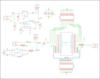
Probably the biggest change was removing the onboard 4020 divider; I just don't see any reason I'd want this, so I ditched it. I also added a TCXO directly on the board; it's surely a vast improvement over a cheap canned oscillator, and simple enough to add a jumper allowing external clock instead if I decide I want to use my OCXO or eventually come up with some other 10MHz 'lab standard'. Finally I went all surface-mount and changed out the 78Lxx regulators for smaller SMD ones with better specs. Other than that the design is virtually identical: an IDT ICS525 programmable PLL clock generator and some DIP switches to set its configuration pins.
I briefly considered using a programmable chip and some sort of PC interface to select the PLL parameters, mostly to save the cost of DIP switches, but I found some cheap suitable ones, so ended up just doing the simple tried-and-true design.
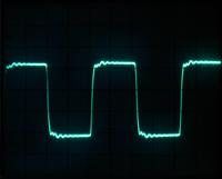
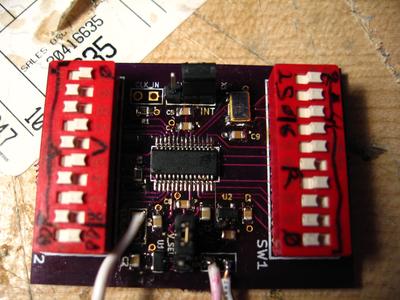
Ultimately the design worked perfectly, but I made one error - the series termination resistor R2 on the output somehow got omitted from the PCB design! The waveform is an absolute disaster without it, but it's an easy enough workaround to solder the resistor sticking out of the output terminal. I had a 57Ω on hand so I used that instead of the 33Ω that IDT recommends, but it worked fine, the waveform is nice now. Other than that omission, assembly was pretty straightforward SMT stuff.
Unfortunately hacking it into my WRAP board I managed to brick it, I think I may have cut too deep into the board and knicked a trace on a middle layer, since the clock signal appears to be perfect on the expected pads, but the machine doesn't even start to boot. So it's offline for now. I'm wondering if my ATNGW100 might work as a reasonable replacement. I hacked a kernel module to use the AVR32's external interrupt to generate timestamps (and since stupidly deleted the sourcecode :o), but it didn't perform as well as the WRAP. Perhaps with this clock module it will be better.
I'm not going to release the bugged gerbers or project files directly on the site, but if you'd like them, feel free to e-mail me.
The scope image is 1V/div at 4.8MHz using the onboard 10MHz FOX924B oscillator as clock source at 3.3V with a 5V input. The first build was with the higher-grade ICS525-02. I'm really not sure how much difference it actually makes since a maximum jitter deviation of < 0.2ns should be well into the noise, even if such short-term errors were visible in an application such as NTP. But what the hell, it only cost a couple bucks more!